3 CONSIDERATIONS WHEN CREATING AND USING VISUALISATIONS OF COMPLEX ENVIRONMENTS
3 CONSIDERATIONS WHEN CREATING AND USING VISUALISATIONS OF COMPLEX ENVIRONMENTS
Date: 8th February 2023
What do you need to consider before signing on the dotted line?
A visualisation is a valuable tool for many of the organisations I work with - particularly if the project or site they’re working on is highly complex. But, the decision to add a visualisation to your arsenal of tools and documentations is one that often comes with a whole host of questions and considerations. The problem is often knowing where to start.
So, here are 3 things you might want to consider when starting on a large-scale visualisation of a complex environment…
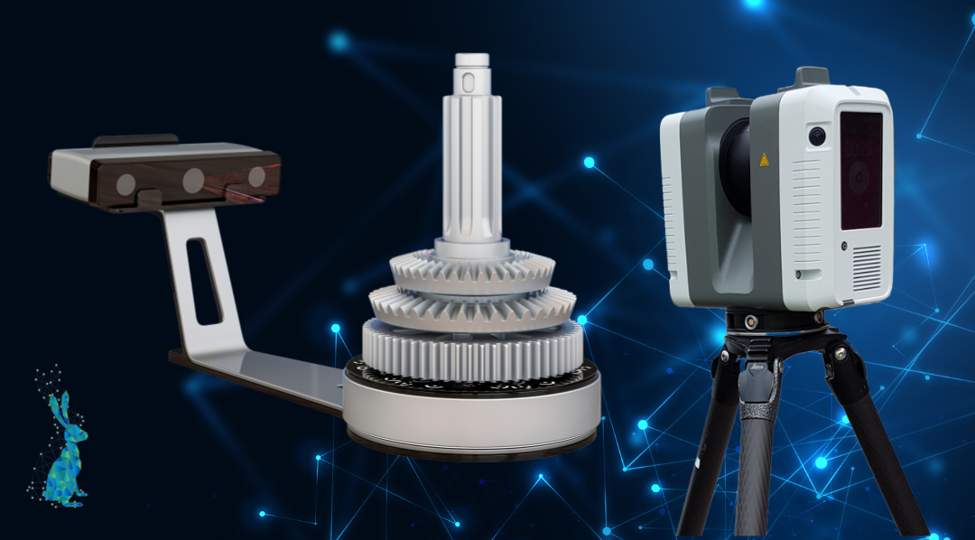
1. For most retrofitting or large scale projects you’re probably going to need 3D laser scan data to work from.
If you’re looking to create the most accurate visualisation of your shop floor or complex environment, you’re going to need an accurate frame of reference to work from. Using 3D laser scan data as your base to build your visualisation from will not only help you to identify the correct layouts, sizing and render as what it was on the day, but will also make the job quicker and easier as you have a frame of reference and aren’t starting from scratch.
It’s important to consider this requirement as, depending on the size of the site you’re looking to create a visualisation of, it can require your designer to be on site for a few days to collect this information.
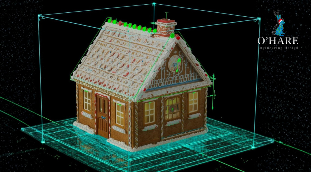
2. The post processing phase of any internal environment requires a specific site coordinate system rather than GPS coordinates.
Plant design using GPS coordinates just doesn't work… And this is because (as I had it described to me by an IT geek!) AutoCAD Plant 3D works on the same principle as most computers do with computer mathematics. In the same way that your RAM goes up from 2Gb to 4Gb to 8Gb to 16Gb (and so on…) the coordinate systems in AutoCAD do the same. The issue is, when these numbers start getting ridiculous and you start trying to draw a line from A to B, the distance between A and B might end up being 2 metres rather than the 200 millimetres you were trying to achieve. This is because it can't stretch the line beyond its limit and the coordinates have reached the extremes of what the software can accurately process.
So instead, projects like this usually require a site coordinate system based on what you’re trying to achieve so that you can have the most accurate and complete image when it comes to post processing.
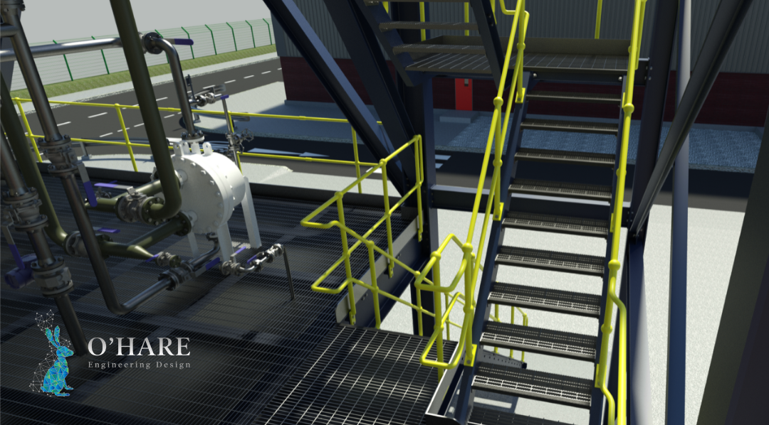
3. The gigantic file size of your final visualisation.
It never fails to amaze me quite how big these highly detailed files can turn out. I’ve been caught out enough times to know that this is an important consideration when thinking about a project because it might be that you only actually need a visualisation of a specific area or piece of equipment and a 3D model might be enough for the rest of the site. If you’re not sure which level of detail would best suit your project, have a word with your mechanical designer who will be able to advise.
Visualisations are a useful tool for any engineer looking to relay their ideas to a board of stakeholders or for retrofitting equipment. If you’d like to find out more, drop us an email today at enquiries@ohare-eng.co.uk.