WHAT'S THE DIFFERENCE BETWEEN VISUALISATION AND 3D MODELLING?
WHAT'S THE DIFFERENCE BETWEEN VISUALISATION AND 3D MODELLING?
Date: 21st June 2022
If you’ve ever worked with CAD you’ll have come across these two terms. They are quite often thrown around by designers and used interchangeably, but are they actually different?
In theory, both 3D modelling and visualisation are very similar in the fact that they are both methods of virtually rendering your environment or object. On paper though, they provide two very different outcomes for your project.
The main difference between 3D modelling and visualisation is this…
A 3D model is a more generalist representation of the part or set up a client is looking to implement. A visualisation is a more detailed model where texture can be applied to show the intricacies of the design.
3D modelling
If I handed you a 3D model of a fixture (like the one below), you could easily walk onto the site and be able to apply this image to understand the part in relation to its surroundings. It will show you the broad shape and layout of a site or fixture, it might even be colour coded, but you don't get the same level of intricate details that a visualisation would provide.
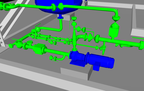
3D model of a process delivery pump
Models like this one would be used within the usual design and site mapping processes. Although they don’t detail the intricacies of the design, 3D modelling does provide the level of design detail required for design and in house fabrication purposes in a shorter time frame.
Visualisation
Visualisation on the other hand, is a more detailed representation of this part, where texture can be applied to create a more accurate model. As you can see in the image below, the instrument looks like the instrument is, the valve looks like the valve and you can see the individual parts and the orientation they will actually be in when positioned on site.
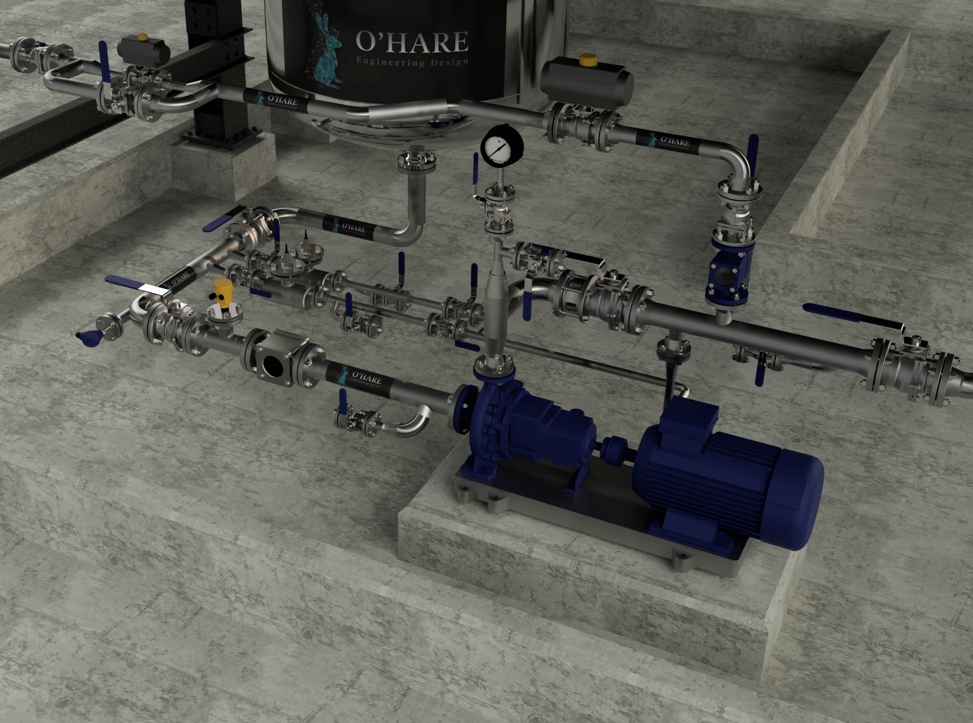
Visualisation of a process delivery pump
This render can take some time to produce due to the added level of detail required, however, you will get the details of every bolt and washer within the visualisation. This is not necessarily required for standard design and fabrication purposes but can be a useful tool for sanity checking the viability of the individual parts and elements of the design. For example, depicting accurate handle designs for the valve within this design could help determine the final orientation of the valve and the shape of the handle if it needs to fit in around other parts.
Having these smaller details available will help communicate the design intent between the design team, fabrications team and construction team. This will save time in the long run as it will mean less questions will be passed back and forth during the construction phase.
The high level of detail available in visualisations also makes them invaluable training materials within organisations and environments where the pipework or fixtures are not easily accessible. Some clients also use visualisations like the one above as marketing materials to share with potential shareholders and stakeholders. These designs show potential investors exactly what they’re going to get to to help demonstrate the viability of the project as well as the physical outcome.
Does this get your cogs turning? To find out more about how 3D modelling and visualisation could benefit your business, book a free design consultation today at
https://www.ohare-eng.co.uk/contact.


We are a highly skilled design and project engineering consultancy, based in the North-West, with more than 20 years experience.