The different types of engineering design drawings and what they’re used for…

The different types of engineering design drawings and what they’re used for…
Date: 27th November 2024
Engineering design projects, especially in chemical plants, often involve multiple teams and many moving parts. In such complex environments, ensuring everyone is aligned is critical. When miscommunication occurs, it’s often due to one culprit: inaccurate or mismatched drawings.
From high-level layouts to detailed system schematics, each type of drawing plays a unique and vital role. This blog delves into the essential engineering drawings used in chemical plant design, highlighting how they promote safety, efficiency, and effective collaboration among teams.
1. General Arrangement (GA) Drawings
General Arrangement (GA) drawings give an accurate overview of a plant’s physical layout, including the placement of all major equipment, pipes, and structural elements. They are typically created in plan (top-down) and elevation (side) views, offering a comprehensive overview of equipment and piping arrangements. They also use sections and elevations to show multiple angles and layouts, making it easy to visualise how each component fits together within the plant.
For a piping engineer, GA drawings are invaluable for coordinating designs with other engineering teams, such as civil, structural, and electrical. This ensures that piping systems fit precisely within the plant’s layout. GAs also help identify potential spatial issues early, so adjustments can be made to avoid issues during construction. This is important for efficient planning, ensuring that all elements are accessible for maintenance and meet space and safety requirements.
In the UK, GAs are commonly designed to adhere to BS EN ISO standards, ensuring uniformity and compliance with national safety regulations. Following these standards helps maintain consistency and is essential in heavily regulated environments like chemical plants, where safety is a top priority.
2. Piping and Instrumentation Diagrams (P&IDs)
P&IDs are detailed diagrams of how your system will work in relation to the rest of the plant. These drawings are functional rather than scaled, focusing on the relationships between different system elements rather than exact dimensions.
Design engineers use this to source materials and map out the route for the proposed pipework to enable accurate and efficient manufacturing of the system. A P&ID will typically show the types and locations of valves, instruments, sensors, and control devices, with details about their function within the process. During the design phase, these diagrams clarify how each process component interacts, and they serve as a reference throughout the plant’s lifecycle, from construction and commissioning to operation, maintenance, and troubleshooting.
P&IDs act as a bridge between the broader plant layout in GA drawings and the specific details in isometric drawings. They define how each component functions, informing layout and installation decisions.
3. Process Flow Diagrams (PFDs)
Process Flow Diagrams (PFDs) are vital in chemical plant design, offering a high-level overview of the entire process. They detail major equipment, process lines, and flow directions while highlighting operational parameters like pressure and temperature. Unlike P&IDs, PFDs focus on the overall process rather than intricate control systems, making them indispensable for initial planning and communication across teams. By simplifying complex systems, PFDs help engineers and stakeholders understand key workflows, identify inefficiencies, and guide more detailed design phases.
4. Isometric Drawings (Isos)
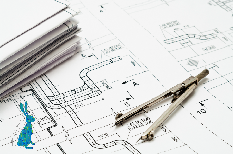
Isometric drawings, or isos, present a three-dimensional view of piping layouts in a 2D format. These drawings focus on specific pipe runs, showing their exact length, angles, fittings, and dimensions. Isometric drawings are among the most detailed engineering drawings and are essential for piping fabrication and installation.
Isos contain key information about each pipe, such as lengths, angles, weld points, valve positions, and materials. These drawings also include notes on construction requirements, such as weld types, and flange specifications. Each component is labelled with precise measurements to guide fabricators and installers.
Isometric drawings provide a detailed blueprint for constructing piping sections. This accuracy ensures that all piping components are manufactured to the correct specifications, reducing errors and rework during installation. They are also useful for performing stress analysis, as they allow engineers to predict how pipes will behave under different conditions, such as high pressure or temperature.
5. Site Layouts
Site layouts offer a high-level view of the entire plant’s layout, showing the location of key areas, roads, boundaries, and major plant elements. They are typically created in the early planning stages to ensure that all necessary components fit within the plant’s physical space and that the site complies with zoning, environmental, and safety regulations. This drawing is often used by both the client and the regulatory bodies to confirm that the plant’s design meets all regulatory and logistical requirements.
For piping engineers, site layout plans provide a basis for laying out piping systems while ensuring compatibility with the site’s physical constraints. They’re also essential for emergency planning and ensuring safe access to critical areas.
Conclusion
Engineering design drawings are indispensable tools in piping design, guiding engineers from planning through to construction and maintenance. Each drawing type supports the others, forming a network of detailed information that is essential for safe and efficient plant operations. As a piping engineer, mastering these drawings and adhering to UK standards will ensure that your designs contribute to a reliable, safe, and compliant chemical plant.
If you’re missing any of these key drawings for your site, get in touch today.


